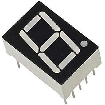
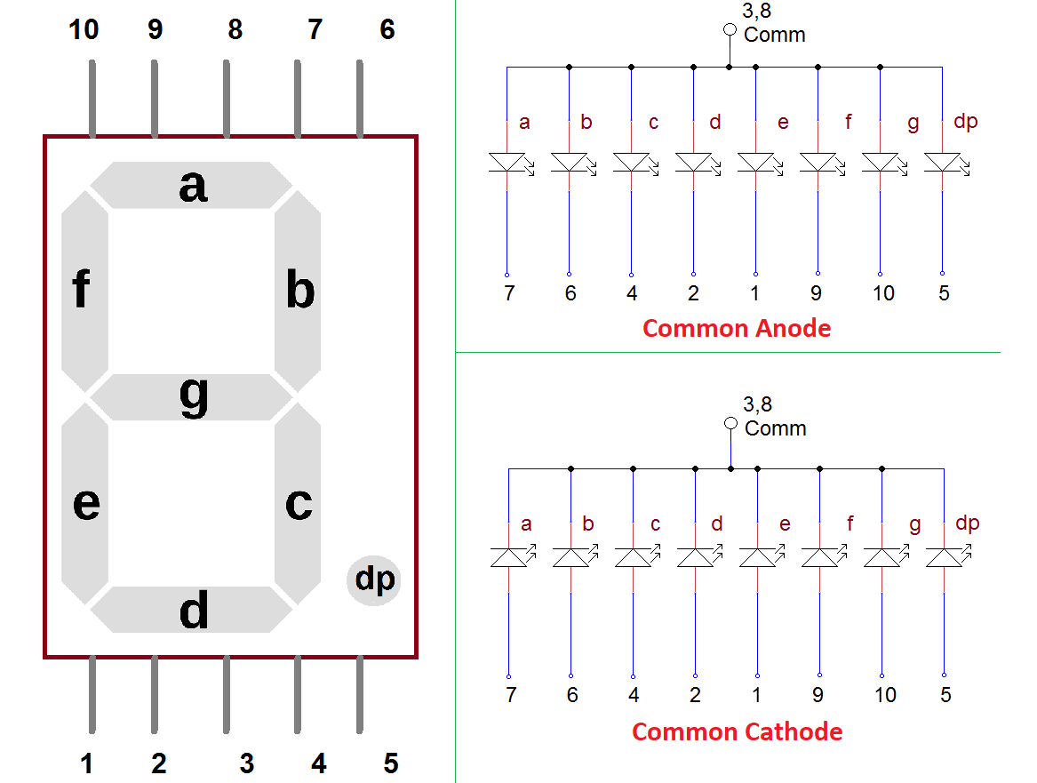
Seven Segment display
NodeMCU
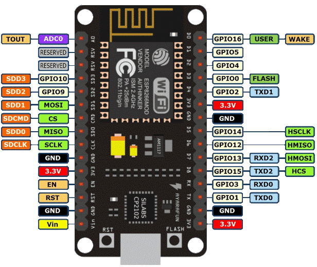
Pin Configuration
Seven segment and NodeMCU pin connections
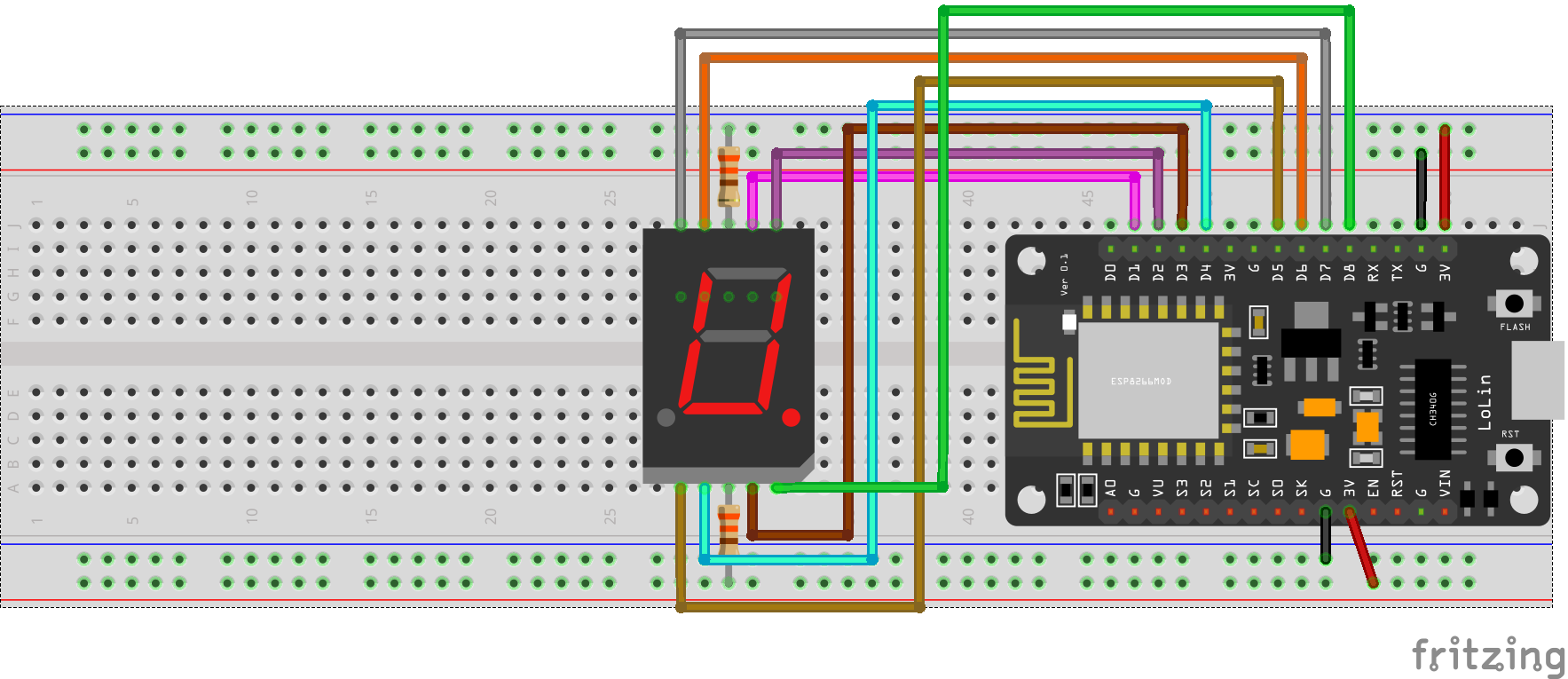
const int A = D1;
const int B = D2;
const int C = D3;
const int D = D4;
const int E = D5;
const int F = D6;
const int G = D7;
const int DP = D8;

void setup() {
  pinMode(A, OUTPUT);
  pinMode(B, OUTPUT);
  pinMode(C, OUTPUT);
  pinMode(D, OUTPUT);
  pinMode(E, OUTPUT);
  pinMode(F, OUTPUT);
  pinMode(G, OUTPUT);
  pinMode(DP, OUTPUT);
}

void loop() {
  ZERO();
  delay(1000);
  ONE();
  delay(1000);
  THREE();
  delay(1000);
  FOUR();
  delay(1000);
  FIVE();
  delay(1000);
  SIX();
  delay(1000);
  SEVEN();
  delay(1000);
  EIGHT();
  delay(1000);
  NINE();
  delay(1000);
}

void ZERO(){
  digitalWrite(A, LOW);
  digitalWrite(B, LOW);
  digitalWrite(C, LOW);
  digitalWrite(D, LOW);
  digitalWrite(E, LOW);
  digitalWrite(F, LOW);
  digitalWrite(G, HIGH);
  digitalWrite(DP, HIGH);
  }
void ONE(){
  digitalWrite(A, HIGH);
  digitalWrite(B, LOW);
  digitalWrite(C, LOW);
  digitalWrite(D, HIGH);
  digitalWrite(E, HIGH);
  digitalWrite(F, HIGH);
  digitalWrite(G, HIGH);
  digitalWrite(DP, HIGH);
  }
void TWO(){
  digitalWrite(A, LOW);
  digitalWrite(B, LOW);
  digitalWrite(C, HIGH);
  digitalWrite(D, LOW);
  digitalWrite(E, LOW);
  digitalWrite(F, HIGH);
  digitalWrite(G, LOW);
  digitalWrite(DP, HIGH);
}
void THREE(){
  digitalWrite(A, LOW);
  digitalWrite(B, LOW);
  digitalWrite(C, LOW);
  digitalWrite(D, LOW);
  digitalWrite(E, HIGH);
  digitalWrite(F, HIGH);
  digitalWrite(G, LOW);
  digitalWrite(DP, HIGH);
  }
void FOUR(){
  digitalWrite(A, HIGH);
  digitalWrite(B, LOW);
  digitalWrite(C, LOW);
  digitalWrite(D, LOW);
  digitalWrite(E, HIGH);
  digitalWrite(F, LOW);
  digitalWrite(G, LOW);
  digitalWrite(DP, HIGH);
  }
void FIVE(){
  digitalWrite(A, LOW);
  digitalWrite(B, HIGH);
  digitalWrite(C, LOW);
  digitalWrite(D, LOW);
  digitalWrite(E, HIGH);
  digitalWrite(F, LOW);
  digitalWrite(G, LOW);
  digitalWrite(DP, HIGH);
}
void SIX(){
  digitalWrite(A, LOW);
  digitalWrite(B, HIGH);
  digitalWrite(C, LOW);
  digitalWrite(D, LOW);
  digitalWrite(E, LOW);
  digitalWrite(F, LOW);
  digitalWrite(G, LOW);
  digitalWrite(DP, HIGH);
  }
void SEVEN(){
  digitalWrite(A, LOW);
  digitalWrite(B, LOW);
  digitalWrite(C, LOW);
  digitalWrite(D, HIGH);
  digitalWrite(E, HIGH);
  digitalWrite(F, HIGH);
  digitalWrite(G, HIGH);
  digitalWrite(DP, HIGH);
  }
void EIGHT(){
  digitalWrite(A, LOW);
  digitalWrite(B, LOW);
  digitalWrite(C, LOW);
  digitalWrite(D, LOW);
  digitalWrite(E, LOW);
  digitalWrite(F, LOW);
  digitalWrite(G, LOW);
  digitalWrite(DP, HIGH);
  }
void NINE(){
  digitalWrite(A, LOW);
  digitalWrite(B, LOW);
  digitalWrite(C, LOW);
  digitalWrite(D, LOW);
  digitalWrite(E, HIGH);
  digitalWrite(F, LOW);
  digitalWrite(G, LOW);
  digitalWrite(DP, HIGH);
  }